Magnetic Fields
A magnetic dipole can be considered similar to that of an electrical dipole with positive and negative as in a current carrying loop of wire but with a magnet it is a north and south pole. Magnetic forces are created by moving electrically charged particles and are best represented as magnetic fields.

A magnetic field is the field or area surrounding a permanent magnet or an electromagnet where the magnetic forces exist. Most of the materials in our universe are non-magnetic. There are certain permanent magnets present and also some materials through which on passing electricity behaves like a magnet. A magnetic field has two poles, and they are North and South poles.
It is never possible to divide a magnetic field. On breaking a magnet, the field will not get divided, but there will be two smaller magnetic fields having both the North and the South Pole. Opposite poles of a magnet attract each other. On the other hand, similar poles will repel each other.
Magnetic field is often represented by lines of force. The lines of force that represent the magnetic field are called magnetic flux. There will always be numerous lines of force within a magnetic field. The lines of force within a magnetic field never intersect or cross each other. These lines of force actually originate from the North Pole and travel towards the South Pole. These lines of force have elastic nature. Whenever they are distorted by external force, they try to get back to their old position.

Magnetic field strength and Magnetisation
Magnetic field strength (H) is the externally applied magnetic field and is described by the relationship between a wire carrying current (I) , the number of turns of that wire (n) and the total length of the wire loops as shown in Figure XX.

If a material exists then the magnetisation (M) represents
Magnetic flux and magnetic flux density
Magnetic flux (Φ or ΦB), is the amount of magnetic field lines passing through a particular surface and is measured in units called Webers (Wb) whereas magnetic flux density is the magnetic flux passing through a particular area at a particular point. Magnetic flux is measured in webers, but magnetic flux density is measured in webers per square meter.
Since the magnetic flux lines are elastic in nature and when opposite poles of a magnet come close to each other, the lines of force try to converge and take the shortest possible path. This creates attraction between the poles. When similar poles of two magnets come in close proximity to each other, due to elastic nature of the flux lines, they take a broader path as the lines of flux gets compressed and create a repulsive force between the poles. The earth is considered the biggest magnet. The flux generated by it is the largest and navigators set their compass based on the flux generated by the earth for determining directions while in the sea or in the air.
Permeability
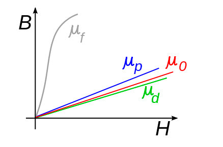
Permeability (µ) refers to the relationship between magnetic field and flux through a medium or material and the resistance to a magnetising field. In a vacuum the permeability (known as permeability of free space) is value µ0 = 4π × 10−7> H•m−1.

The permeability of a material is related to its diamagnetic, paramagnetic and ferromagnetic type as shown in Figure XX.
Magnetic flux density
BH Curves
BH curve (also known as hysteresis curve) is a curve describing the connection between the magnetic flux density and magnetic field strength of a magnetic material. The graph below illustrates BH curves for three different types of materials, steel iron and air.
Notice all three materials’ flux density rise with the increase of their field strength up to a certain level at which the graph almost levels or maintains a constant while still the field strength increases. This point is known as the magnetic saturation point.
Different materials have different magnetic saturation points as reflected in the graph below. Saturation occurs as a result of the magnet domain of a material aligning itself to the magnetic field strength. Hence, magnetic saturation point is the point at which the molecular structure of a material is perfectly aligned at achieving a maximum flux density.

Figure 1 source: http://www.electronics-tutorials.ws/electromagnetism
The opposite of the above diagram can also be achieved when the magnetic field strength increases but in the opposite direction. This happens when the direction of current flowing through a material is reversed taking the magnetic field strength (H) on the graph to the negative until it reaches its magnetic saturation point but on the negative side of the graph.
The constant changing of the direction of current flowing through a magnet to create magnetic field in both directions is what produces hysteresis loop.
HYSTERESIS LOOP
As explained in the last paragraph above, below is a graph explaining hysteresis loop.
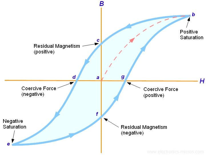
Figure 2 source: http://www.electronics-micros.com
The area enclosed by the graph represents energy lost in the process of reversing the magnetisation or direction of the magnetic field.
At point A, the material is in its un-magnetised state which means that current has not yet been passed through it.
When magnetic current is passed through a material in the positive direction, the magnetic field strength (H) of this material increases in direct proportion with its flux density (B).
Residual magnetism (Br) at point C occurs when the magnetic field strength is reduced to point zero. At this point, the material does not usually lose all its magnetism. The little magnetic force left is what is known as residual magnetism.
The point (B) represents the positive saturation point at which the flux density has reached its maximum while still the field strength increases.
The reverse of this process curves on the negative side of the graph forming the hysteresis loop.
Different materials will exhibit wide or narrow hysteresis loop owing to the hardness or softness of the metal.

Figure 3 source: http://www.electronics-micros.com
The graphs above show the hysteresis loops of two different materials. The larger the hysteresis loop, the more energy a material will need to realign its magnetic molecules when magnetic current is reversed. It also means that a material has high retention and coercive force.
It is also important to note that the energy losses represented by the hysteresis loop is unwanted and causes metals to heat. Heat is one known cause of demagnetisation.
The first graph represents the hysteresis loop of hard ferromagnetic material. An example is hard steel which is mostly used for making permanent magnets.
The second graph shows the energy loss of such materials as silicon steel which lose relatively little energy as compared to the hard ferromagnetic metals. These materials are suitable for making transformers and electric machines which use alternating current in their operation, because of their exposure to constant reversal of magnetism.
The graphs above are also useful for the identification of properties of magnets. Retentivity, residual magnetism, coercive force, reluctance and permeability of materials can be determined at a glance from these graphs.

